Using the Analog Output (DAC) (0-10V)


|
|
|
|
Using the Analog Output (DAC) (0-10V)
|
|
Please, before using the DAC output, read this table here: LadderDIP IV Development Board parameters. Exceeding max load currents onto this signal will turn in a permanent damage |
LadderDIP IV Development Board has an on-board DAC (Digital to Analog Converter) output that can generate a 0 to 10V voltage. This resources is accessible, in the Ladder diagram, using the DAC function block.
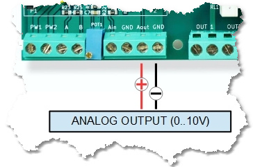
At PCB level, this output is named AOUT
The DAC block has an unique input pin, where the applied value, is directly transferred to the DAC hardware
The DAC function uses the internal LadderDIP IV Digital to Analog converter which has a 10 bits resolution (0..1023 values)
In order, to use the AOUT output with the DAC block, follow the listed instructions
| • | Use the DAC block configuring the CHANNEL parameter according to the following table |
ANALOG OUTPUT |
CHANNEL |
AOUT |
0 |
Now we can try how the TRIMMER works opening the project named "DAC" which is located at "..\projects\samples\ladderbox\dac\dac.lww"
The following diagram will appear
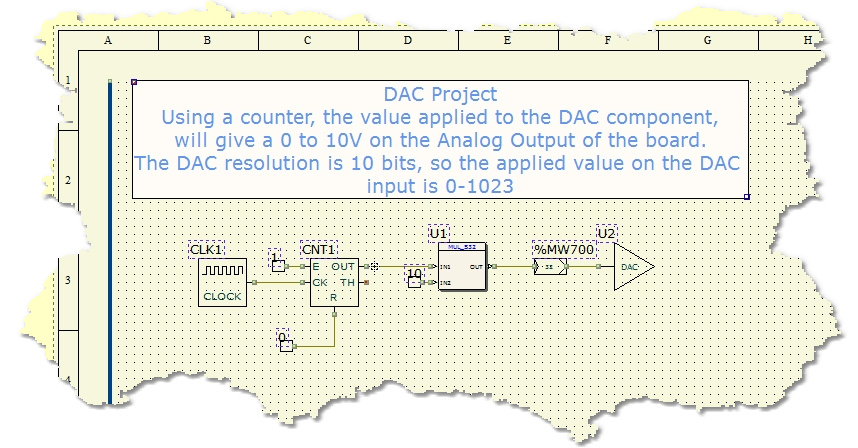
To see this project working you need to connect a multimeter or an oscilloscope on the analog output plugs. What you will see will be a ramp of voltages spanning from zero to almost 10 volts
Once everything is ready you can press the Build All button ![]() (Also indicated as Build & Upload & Run in the build menu command), this will execute all the necessary operations to download and run a program into the LadderDIP IV Development Board
(Also indicated as Build & Upload & Run in the build menu command), this will execute all the necessary operations to download and run a program into the LadderDIP IV Development Board
module. The executed processes will be: Compile, connect, erase, download and run. These processes will be accomplished by dialogs and progression bar to check the current status of operations
