Using the On-Board Trimmer


|
|
|
|
Using the On-Board Trimmer
|
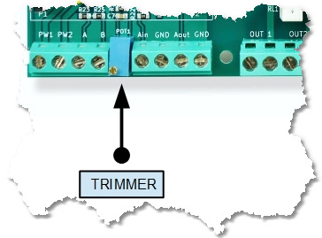
LadderDIP IV Development Board has an on-board trimmer that generates an internal analog voltage. This resources is accessible, in the Ladder diagram, using the AD_CONV function block.
This block has an unique output pin that gives the value of the converted analog input. The output value can span from 0 to 4095 (16 bits)
In order, to use the trimmer with the AD_CONV block, follow the listed instructions
| • | Use the AD_CONV block configuring the CHANNEL parameter according to the following table |
ANALOG INPUT |
CHANNEL |
TRIMMER |
5 |
| • | Also configure the AD_CONV block with the following parameters |
PARAMETER |
VALUE |
NOTE |
SPAN |
1 |
|
OFFSET |
0 |
|
Internally, the trimmer analog voltage is connected to the analog input AIN6 (P2-32) on the LadderDIP IV module
Now we can try how the TRIMMER works opening the project named "Trimmer" which is located at "..\projects\samples\ladderbox\trimmer\trimmer.lww"
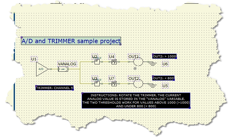
Once you opened the project the following diagram will appear
Once everything is ready you can press the Build All button ![]() (Also indicated as Build & Upload & Run in the build menu command), this will execute all the necessary operations to download and run a program into the LadderDIP IV Development Board
(Also indicated as Build & Upload & Run in the build menu command), this will execute all the necessary operations to download and run a program into the LadderDIP IV Development Board
module. The executed processes will be: Compile, connect, erase, download and run. These processes will be accomplished by dialogs and progression bar to check the current status of operations
If everything is ok you will see the project running. This is the project behaviour (You need a small screwdriver to rotate the TRIMMER)
| • | The analog voltage, generated by the TRIMMER network, is stored in the variable named VANALOG (Connected to the A/D channel 5) |
| • | The A/D range is 0-4095 (12 Bits) |
| • | A threshold component (U2) is configured to activate its output when the value is above 1000, when this occurs the corresponding output is activated |
| • | A second threshold component (U3) is configured to activate its output when the analog value is under 800, when this happen the output is activated |
| • | The two DEBOUNCE blocks (U4/U7), configured with a convolution time of 100mS, are used to filter spikes and noises present on the analog input |