Using the "RELAY" outputs


|
|
|
|
Using the "RELAY" outputs
|
|
LadderDIP IV Development Board mounts LOW-LOAD relays. Carefully observe current and voltage limits when attaching load to these outputs. Please, before using relays, read this table here: LadderDIP IV Development Board parameters |
LadderDIP IV Development Board have eight on-board relays that could be used to drive loads. The relays are configured as NO (Normally Open) contacts. This means that, normally, when the relay is not driven, the contact is open.
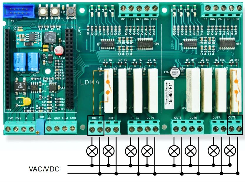
The picture above shows how to connect simple lamps to the eight available relay outputs.
Let's start with a practical example. The objective of this first project is to blink a relay using a very simple project called RelayBlink.
Follow the steps listed here below
| • | Launch the LadderDIP PLC Studio software |
| • | Open the RelayBlink project "..\projects\samples\ladderbox\relayblink\relayblink.lww", the following diagram should appear |
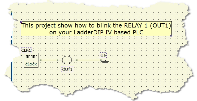
The project is very easy and it takes just two components. The CLOCK component generates a train of 1Hz pulses feeding the output named OUT1 (Logically related to RELAY 1)
Now it is time to run your project
Follow the next instructions
| • | Check your Ethernet port configuration accessing, from the menu, the Options |
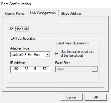
Please carefully check the following parameters:
| • | The "Use Lan" Check must be set |
| • | The "Adapter Type" must be set to "LadderDIP Eth. Port" |
| • | The "IP Address" must be the one set for the module |
|
IMPORTANT NOTE
LadderDIP PLC Studio uses the Ethernet port of your PC. You could have Firewalls or Anti-Viruse softwares that block any access to this resource
Please properly configure, if you have installed in your PC, any Firewall or protection that locks the access to the Ethernet Port
|
TESTING THE CONNECTION OF LadderDIP PLC Studio with LadderDIP IV Development Board
Read the following paragraph to check the connection: Checking connection
At this point, using the LadderDIP PLC Studio software, you can check if the connection is OK simply pressing the connect button ![]()
| • | Once everything is ready you can press the Build All button |
module. The executed processes will be: Compile, connect, erase, download and run. These processes will be accomplished by dialogs and progression bar to check the current status of operations
If everything is ok you will see the project running. You can see the OUT1 blinking and you can also hear the relay clicks ... enjoy it
