Using the "INSULATED" inputs


|
|
|
|
Using the "INSULATED" inputs
|
|
Please, before using opto-insulated inputs, read this table here: LadderDIP IV Development Board parameters. Exceeding max voltages will turn in a permanent damage |
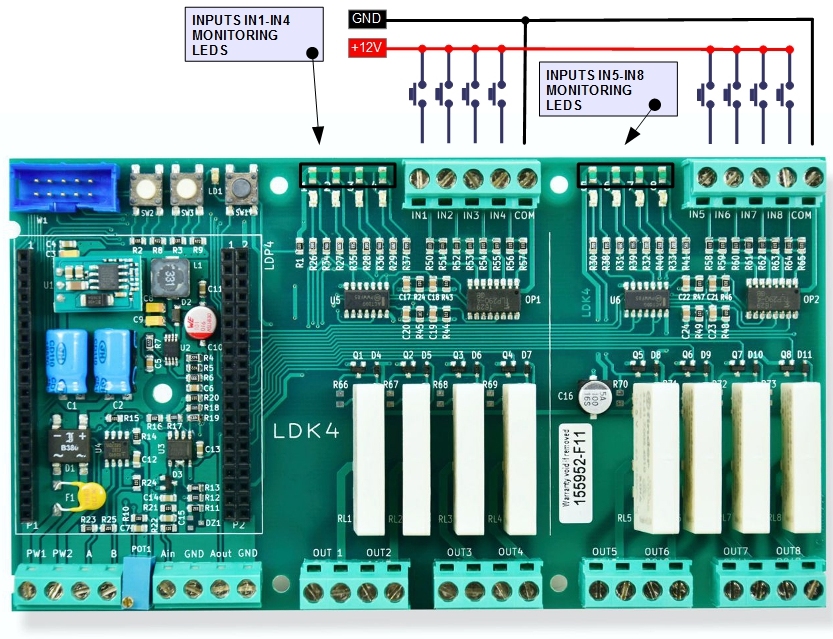
LadderDIP IV Development Board have eight on-board opto-insulated inputs that could be used to connect external switches or direct voltages. On board led(s) are available to monitor inputs state (led off = no signal, on = signal present)
It is time for a practical example. We will run a first project that uses the opto-insulated inputs associated with the INPUT input block
Follow the steps listed here below
| • | Launch the LadderDIP PLC Studio software |
| • | Open the project "..\projects\samples\ladderdip4\ledblink\inputs.lww", the following diagram should appear |
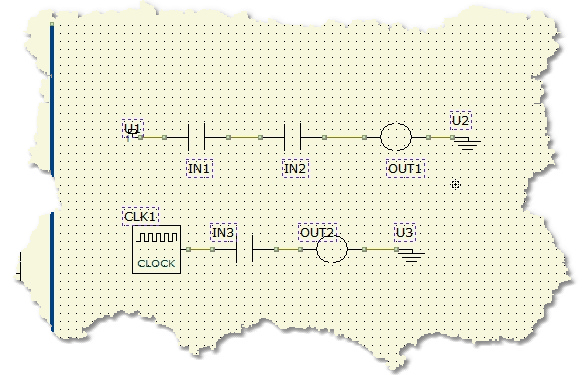
Now, the project has two sections, in old LADDER programs they are called RUNGS. These two portions of diagrams works as parallel processes.
The first section, formed by IN1, IN2 and OUT1 forms an "AND" function. The OUTPUT OUT1 is activated only when the two INPUTS (IN1 and IN2) are active
There is a direct relationship between the names applied on the diagram (IN1, IN2 and OUT2), and the phisical connection on LadderDIP IV Development Board board, so,
the INPUT IN1 correspond to the phisical clamp named IN1, same concept for all the rest of signals.
Applying a voltage to the opto-insulated inputs will activate the corresponding signal (or function block) on the diagram. The LED monitor on the PCB will also turn on when the corresponding signal is activated.
Now, as we already made for the previous projects, it is time to run everything
At this point, using the LadderDIP PLC Studio software, you can check if the connection is OK simply pressing the connect button ![]()
| • | Once everything is ready you can press the Build All button |
module. The executed processes will be: Compile, connect, erase, download and run. These processes will be accomplished by dialogs and progression bar to check the current status of operations
If everything is ok you will see the project running. This is the project behaviour:
| • | OUTPUT OUT1 is activated when both IN1 and IN2 are active. You have to apply a 12VDC voltage to both the inputs, in order, to see the output on. For |
| • | The OUTPUT OUT2 will blink at 1Hz frequency when the IN3 is active (Signal is transferred from CLK1 to OUT2 passing through IN2) |
You can see how these two portions of diagrams work in distinct parallel mode
