Analog threshold with hysteresis


|
Analog threshold with hysteresis |
|
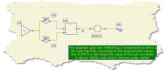
In this application note we introduce other important components like the AD_CONV (Analog to Digital Converter) and the THRESHLD (Threshold). The diagram shows how to create a threshold control with hysteresis circuit.The circuit is really simple and it takes just five components. The AD_CONV component gives, on its single output, the numeric value converted by a physical A/D converter on the PLC. The value is applied to two different comparators ( THRESHLD component ) to create the threshold gap.
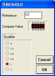
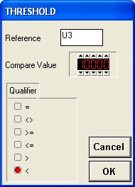
For example, the high-side comparator (TH2) was programmed to be true when the input signal is greater of 40.000 and the low-side comparator was programmed for values less than 10.000.
Remember that the values supplied by AD_CONV conponents are always normalized in the range 0-65535 independantly by the A/D circuit resolution. The signals coming from the comparators are connected to a SR block ( SET-RESET FLIP-FLOP WITH RESET DOMINANT FEATURE ) and the Q output of this function block is suitable for load driving.
With respect with the example programmed values , the Q output will become active for values greater than 40.000 and will be released for values less than 10.000
Here are the properties of any component
|
|
|
As you can see the THRESHOLD component can be programmed to set its output according to the specified condition. In this case the U2 component will activate its output for values above 4000 and U3 will be set on for values under 10000.
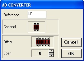
Note the the CHANNEL parameter in the AD_CONV Dialog properties selects from which physical A/D converter take the analog value. The OFFSET and SPAN parameters are useful to change A/D dynamics and gain
At this point you can run the project. Changing voltage, in the A/D specified range, will cause the OUTPUT to be ON or OFF according to the analog value. In the RANGE 10000 to 30000 there is a dead-band where no changes are applied (Hysteresis gap)
Note that this circuit is the typical Water level control. The A/D converted value can be the level of the water and the OUTPUT can be connected (In negated state) to a pump which will control the flow inside the tank. When the water level is under "10000" the pump is run and the water begin to flow into the tank. The process is stopped when the water level reach a value of "40000".