Basic diagram elements


|
Basic diagram elements |
|
In this paragraph we'll introduce the basic elements of a Ladder Diagram. Essentially the Ladder language take concepts, symbolism and philosophy directly by a real electrical circuit. As you can see in the pictures there are basic elements that directly represents the same functions of a hardware switch and a real lamp. These objects are normally referred as Input/Output objects.
Let us introduce to you our first two very basic components. These components ALWAYS are present in any Ladder environment. This objects are called INPUT and OUTPUT
|
INPUT component |
|
|
|
OUTPUT component |
|
|
|
|
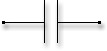
![]() The INPUT component is the object that allow you to ENTER an information to the PLC. This information, in this case, is a BOOLEAN value (0/1 or TRUE/FALSE) and it comes from a real electrical signal of the PLC hardware. The INPUT block reflects the value applied on the left-side pin on the right-side pin when the associated signal (We'll discuss about it later) is TRUE or ASSERTED.
The INPUT component is the object that allow you to ENTER an information to the PLC. This information, in this case, is a BOOLEAN value (0/1 or TRUE/FALSE) and it comes from a real electrical signal of the PLC hardware. The INPUT block reflects the value applied on the left-side pin on the right-side pin when the associated signal (We'll discuss about it later) is TRUE or ASSERTED.
![]() The OUTPUT component is the object that allow you to EXIT an information from the PLC. Like the INPUT block, this information is always a BOOLEAN information and it will cause the associated physical output to reflect the value of the left-side pin. The right-side pin of this component simply reflects the value of the input pin (left-side)
The OUTPUT component is the object that allow you to EXIT an information from the PLC. Like the INPUT block, this information is always a BOOLEAN information and it will cause the associated physical output to reflect the value of the left-side pin. The right-side pin of this component simply reflects the value of the input pin (left-side)