
A first project, the basic I/O Transfer


|
A first project, the basic I/O Transfer |
|
At this point, once we understood the function of the basic I/O blocks we can easily start with our first project. This project aims to transfer an input of the PLC to an output. The signal applied on the desired INPUT will be transferred to the configured OUTPUT. The project consist of three components only
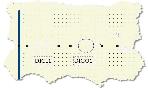
The diagram in the picture is also called "RUNG". A Ladder diagram can be formed by an undefined number of rungs. If you take a look to the picture you can see other important elements that enter in play in this kind of language. The BAR present on the LEFT of the schematic is called the POWER BAR and it represents the "source of electricity" for your elements. Like any real electrical circuit this object represent the way to supply power to the components.
The other important element is the GROUND component (GND). This component, always like you do in a regular electrical plant, allow you to "close" the circuit and allow the current flow.
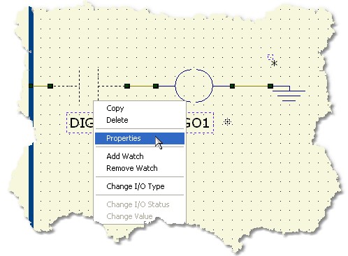
At this point the next step is to associate the INPUT and OUTPUT block to a physical signal on the PLC. This procedure is accessible selecting the Properties entry from the menu related to the component. This is activated selecting the component with the left mouse button and clicking on its symbol with the right mouse button.
This procedure allow you to enter the configuration Dialog of a component. For component like INPUT and OUTPUT the software allow you to select a PHYSICAL signal of the PLC. This signals are accessible through mnemonic names that you can change for your purposes.
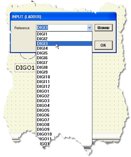
You have to configure both the INPUT and OUTPUT block associating, respectively, an INPUT signal and an OUTPUT signal. Press the OK button to confirm any changes
This tutorial does not consider the final hardware you are working on so refer to your hardware manual for PLC setting-up and connections.
Once everything is ready you can press the Build All button ![]() (Also indicated as Build & Upload & Run in the build menu command), this will execute all the necessary operations to download and run a program into your PLC. The executed processes will be: Compile, connect, erase, download and run. These processes will be accomplished by dialogs and progression bar to check the current status of operations
(Also indicated as Build & Upload & Run in the build menu command), this will execute all the necessary operations to download and run a program into your PLC. The executed processes will be: Compile, connect, erase, download and run. These processes will be accomplished by dialogs and progression bar to check the current status of operations
Once the program is correctly loaded and running you can apply the input signal to the configured physical input and see the signal reflected to the specified output.
For further information about these components see INPUT and OUTPUT .