
A more complex project, a basic counter


|
A more complex project, a basic counter |
|
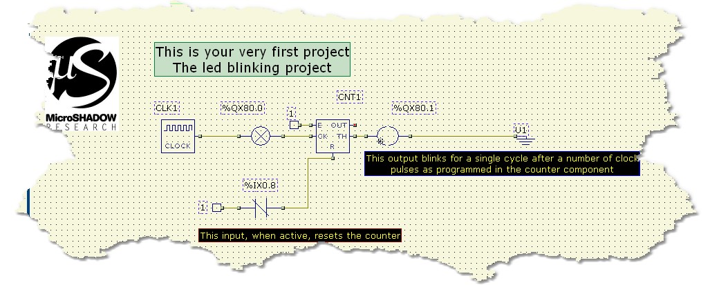
Now that we are familiar with many elements we can start with a more complex project. This diagram introduces a new component called COUNTER. This object allow to count pulses applied to its input giving the total count value on the output. The COUNTER object acts like a "ring counter". Accessing the properties of this component you can configure this block to count in a predefined range (Allowable values are from 0 to 65535).
The enable (E) input allow you to enable or disable the counting. The reset (R) input acts like an asyncronous reset of the count. The threshold (TH) pin become TRUE when the counting value reach the maximum programmed value. This object can be programmed to count up or down.
In the diagram there are other new elements we are going to describe. The first component is called IDENT and allow you to enter constant values in the diagram. In this case this object is used to enter the value 1 (TRUE) to the enable input of the counter, this makes the COUNTER working properly. The IDENT component, when configured with the value 1, is also equivalent to the left power bar of any Ladder diagram. Often programmers prefers to use this method allowing less wiring and a more clear schematic. As you can see on this project the IDENT component is also used to feed a NCINPUT (Normally closed INPUT) on its left pin. This little piece of diagram allow to apply a reset to the COUNTER
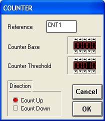
The COUNTER properties Dialog looks like here
Now, what we would aim from this project is to divide a certain number of pulses by 11. The diagram is very intuitive and since you are now very well-versed with this language you already understood what you will get.
A CLOCK component is feeding an OUTPUT block that will flash the programmed signal to the base programmed frequency (For example 1Hz). The right-side pin of the OUTPUT block transfer the same square-wave signal to the clock input of the COUNTER. The threshold output of the COUNTER is connected to a second OUTPUT and it will be ON when the counter will reach the value 10. Pratically this works like a by-11 divisor. Once the value 11 is reached the counter will reset to zero again and a new cycle will be started.
What we expect by this project?
Once you load and run this project on your PLC you will see the first OUTPUT blinking at 1Hz frequency. After 10 pulses you will see the 2nd OUTPUT become ON and after a pulse it returns to OFF again. The cycle is repeated forever ... at least if you don't remove the power from your PLC ...
Click the link for a better description of the COUNTER component