Using the Analog Input (0-10V)


|
|
|
|
Using the Analog Input (0-10V)
|
|
VERY IMPORTANT Carefully respect the max voltage values as written in the product specifications
Refer to this table: DC/AC Parameters and absolute max ratings |
There is one on-board A/D (Analog to Digital Converter) 0-10V input on LadderDIP IV Development Board. This resources is accessible, in the Ladder diagram, using the AD_CONV function block.
This block has an unique output pin that gives the value of the converted analog input. The output value can span from 0 to 4095 (16 bits)
In order, to use the analog input with the AD_CONV block, follow the listed instructions
| • | Use the AD_CONV block configuring the CHANNEL parameter according to the following table |
ANALOG INPUT |
CHANNEL |
AIN(0-10V) |
3 |
| • | Also configure the AD_CONV block with the following parameters |
PARAMETER |
VALUE |
NOTE |
SPAN |
1 |
|
OFFSET |
0 |
|
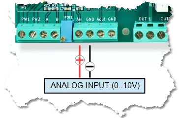
Internally, the 0-10V analog input is connected, through an operational amplifier, to the analog input AIN4 (P1-15) on the LadderDIP IV module
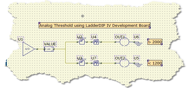
Now we can try how the 0-10V analog input works opening the project named AnalogThresholds which is located at "..\projects\samples\ladderbox\analogthresholds\analogthresholds.lww"
Once you opened the project the following diagram will appear
NOTE: To test this project i need a voltage source applied between the AIN and the GND screw connector. You can use a simple battery (For example 9V) connected with a trimmer to the AIN input, or, any other voltage source that could span between a range of 0 to 10V is of course good
| • | Once everything is ready you can press the Build All button |
module. The executed processes will be: Compile, connect, erase, download and run. These processes will be accomplished by dialogs and progression bar to check the current status of operations
If everything is ok you will see the project running. This is the project behaviour:
| • | The analog voltage value applied to the AIN input is processed by the AD_CONV component (A/D) |
| • | The converted value, normalized in the range 0..4095, is then written to the variable named VALUE. During the debug the raw value is visible here |
| • | A threshold component (U2) is configured to activate its output when the value is above 2000, when this occurs the corresponding output is activated |
| • | A second threshold component (U3) is configured to activate its output when the analog value is under 1200, when this happen the output is activated |
| • | The two DEBOUNCE blocks (U4/U7), configured with a convolution time of 100mS, are used to filter spikes and noises present on the analog input |
